
Background
The concept of shadow is inseparable from the concept of light, as you need light in order to cast a shadow. There are many techniques that generate shadows and in this two part tutorial we are going to study one of the more basic and simple ones - shadow mapping.
When it comes to rasterization and shadows the question that you ask yourself is - is this pixel located in shadow or not? Let's ask this differently - does the path from the light source to the pixel goes through another object or not? If it does - the pixel is probably in shadow (assuming the other object is not transparent...), and if not - the pixel is not in shadow. In a way, this question is similar to the question we asked ourselves in the previous tutorial - how to make sure that when two objects overlap each other we will see the closer one. If we place the camera for a moment at the light origin the two questions become one. We want the pixels that fail the depth test (i.e. the ones that are further away and have pixels before them) to be in shadow. Only the pixels that win the depth test must be in light. They are the ones that are in direct contact with the light source and there is nothing in between that conceals them. In a nutshell, this is the idea behind shadow mapping.
So it looks like the depth test can help us detect whether a pixel is in shadow or not but there is a problem. The camera and the light are not always positioned in the same place. The depth test is normally used to solve the visibility problem from the camera point of view, so how can we harness it for shadow detection when the light is located further away? The solution is to render the scene twice. First from the light point of view. The results of this render pass don't reach the color buffer. Instead, the closest depth values are rendered into an application created depth buffer (instead of the one that is automatically generated by GLUT). In the second pass the scene is rendered as usual from the camera point of view. The depth buffer that we've created is bound to the fragment shader for reading. For each pixel we fetch the corresponding depth from that depth buffer. We also calculate the depth of this pixel from the light point of view. Sometimes the two depth values will be identical. This is the case where this pixel was closest to the light so its depth value ended up in the depth buffer. If that happen we consider the pixel as if it is in light and calculate its color as usual. If the depth values are different it means there is another pixel that covers this pixel when looking at it from the light position. In this case we add some shadow factor to the color calculation in order to simulate the shadow effect. Take a look at the following picture:
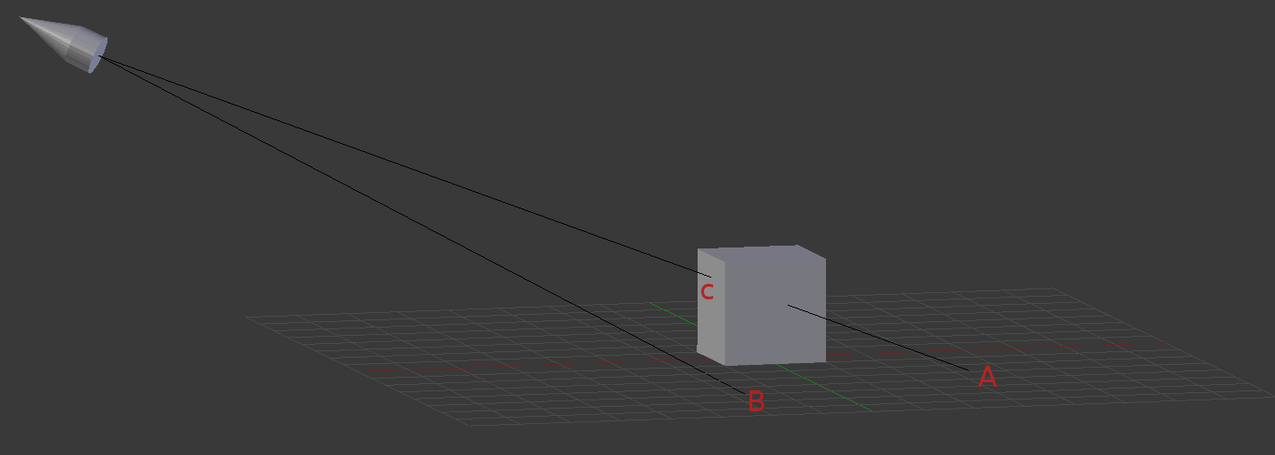
Our scene is made up of two objects - the surface and the cube. The light source is located at the top left corner and is pointing at the cube. In the first pass we render into the depth buffer from the point of view of the light source. Let's focus on the three points A, B and C. When B is rendered its depth value goes into the depth buffer. The reason is that there is nothing in between the point and the light. By default, it is the closest point to the light on that line. However, when A and C are rendered they "compete" on the exact same spot in the depth buffer. Both points are on the same straight line from the light source so after perspective projection takes place the rasterizer finds out both points need to go to the same pixel on the screen. This is the depth test and point C "wins" it.
In the second pass we render the surface and the cube from the camera point of view. In addition to everything we have done in our lighting shader per pixel we also calculate the distance from the light source to the pixel and compare it to the corresponding value in the depth buffer. When we rasterize point B the two values should roughly be same (some differences are expected due to differences in interpolation and floating point precision issues). Therefore, we decide that B is not in shadow and act accordingly. When we rasterize point A we find out that the stored depth value is clearly smaller than the depth of A. Therefore, we decide that A is in shadow and apply some shadow factor to it in order to get it darker than usual.
This, in a nutshell, is the shadow mapping algorithm (the depth buffer that we render to in the first pass is called the "shadow map"). We are going to study it in two stages. In the first stage (this tutorial) we will learn how to render into the shadow map. The process of rendering something (depth, color, etc) into an application created texture is known as 'render to texture'. We will display the shadow map on the screen using a simple texture mapping technique that we are already familiar with. This is a good debugging step as getting the shadow map correct is crucial in order to get the complete shadow effect working correctly. In the next tutorial we will see how to use the shadow map in order to do the "in shadow/not in shadow" decision.
The sources of this tutorial include a simple quad mesh that can be used to display the shadow map. The quad is made up of two triangles and the texture coordinates are set up such that they cover the entire texture space. When the quad is rendered the texture coordinates are interpolated by the rasterizer, allowing you to sample an entire texture and display it on screen.
Source walkthru
(shadow_map_fbo.h:50)
                        class ShadowMapFBO

                        {

                            public:

                                ShadowMapFBO();


                                ~ShadowMapFBO();


                                bool Init(unsigned int WindowWidth, unsigned int WindowHeight);


                                void BindForWriting();


                                void BindForReading(GLenum TextureUnit);


                            private:

                                GLuint m_fbo;

                                GLuint m_shadowMap;

                        };
The results of the 3D pipeline in OpenGL end up in something which is called a 'framebuffer object' (a.k.a FBO). This concept wraps within it the color buffer (which is displayed on screen), the depth buffer as well as a few other buffers for additional usages. When glutInitDisplayMode() is called it creates the default framebuffer using the specified parameters. This framebuffer is managed by the windowing system and cannot be deleted by OpenGL. In addition to the default framebuffer, an application can create FBOs of its own. These objects can be manipulated and used for various techniques under the control of the application. The ShadowMapFBO class provides an easy to use interface to a FBO which will be used for the shadow mapping technique. Internally, this class contains two OpenGL handles. The handle 'm_fbo' represents the actual FBO. The FBO encapsulates within it the entire state of the framebuffer. Once this object is created and configured properly we can change framebuffers by simply binding a different object. Note that only the default framebuffer can be used to display something on the screen. The framebuffers created by the application can only be used for "offscreen rendering". This can be an intermediate rendering pass (e.g. our shadow mapping buffer) which can later be used for the "real" rendering pass that goes to the screen.
In itself, the framebuffer is just a placeholder. To make it usable we need to attach textures to one or more of the available attachment points. The textures contain the actual storage space of the framebuffer. OpenGL defines the following attachment points:
- COLOR_ATTACHMENTi - the texture that will be attached here will receive the color that comes out of the fragment shader. The 'i' suffix means that there can be multiple textures attached as color attachments simultaneously. There is a mechanism in the fragment shader that enables rendering into several color buffers at the same time.
- DEPTH_ATTACHMENT - the texture that will be attached here will receive the results of the depth test.
- STENCIL_ATTACHMENT - the texture that will be attached here will serve as the stencil buffer. The stencil buffer enables limiting the area of rasterization and can be used for various techniques.
- DEPTH_STENCIL_ATTACHMENT - this one is simply a combination of depth and stencil buffers as the two are often used together.
For the shadow mapping technique we will only need a depth buffer. The member attribute 'm_shadowMap' is the handle of the texture that will be attached to the DEPTH_ATTACHMENT attachment point. The ShadowMapFBO also provides a couple of methods that will be used in the main render function. We will call BindForWriting() before rendering into the shadow map and BindForReading() when starting the second rendering pass.
(shadow_map_fbo.cpp:43)
glGenFramebuffers(1, &m_fbo);
Here we create the FBO. Same as in textures and buffers, we specify the address of an array of GLuints and its size. The array is populated with the handles.
(shadow_map_fbo.cpp:46)
                        glGenTextures(1, &m_shadowMap);

                        glBindTexture(GL_TEXTURE_2D, m_shadowMap);

                        glTexImage2D(GL_TEXTURE_2D, 0, GL_DEPTH_COMPONENT, WindowWidth, WindowHeight, 0, GL_DEPTH_COMPONENT, GL_FLOAT, NULL);

                        glTexParameterf(GL_TEXTURE_2D, GL_TEXTURE_MIN_FILTER, GL_LINEAR);

                        glTexParameterf(GL_TEXTURE_2D, GL_TEXTURE_MAG_FILTER, GL_LINEAR);

                        glTexParameterf(GL_TEXTURE_2D, GL_TEXTURE_WRAP_S, GL_CLAMP_TO_EDGE);

                        glTexParameterf(GL_TEXTURE_2D, GL_TEXTURE_WRAP_T, GL_CLAMP_TO_EDGE);
Next we create the texture that will serve as the shadow map. In general, this is a standard 2D texture with some specific configuration to make it suitable for its purpose:
- The internal format is GL_DEPTH_COMPONENT. This is different from the previous use of this function where the internal format was usually one of the color types (e.g. GL_RGB). GL_DEPTH_COMPONENT means a single floating point number that represents the normalized depth.
- The last parameter of glTexImage2D is null. This means that we are not supplying any data by which to initialize the buffer. This makes sense knowing that we want the buffer to contain the depth values of each frame and each frame is a bit different. Whenever we start a new frame we will use glClear() to clear out the buffer. This is all the initialization that we need for the content.
- We tell OpenGL that in case a texture coordinate goes out of bound it needs to clamp it to the [0,1] range. This can happen when the projection window from the camera point of view contains more than the projection window from the light point of view. To avoid strange artifacts such as the shadow repeating itself elsewhere (due to wraparound) we clamp the texture coordinates.
(shadow_map_fbo.cpp:54)
glBindFramebuffer(GL_FRAMEBUFFER, m_fbo);
We have generated the FBO, the texture object and also configured the texture object for shadow mapping. Now we need to attach the texture object to the FBO. The first thing we need to do is to bind the FBO. This will make it "current" and then all future FBO operations will apply to it. This function takes the FBO handle and the desired target. The target can be GL_FRAMEBUFFER, GL_DRAW_FRAMEBUFFER or GL_READ_FRAMEBUFFER. GL_READ_FRAMEBUFFER is used when we want to read from the FBO using glReadPixels (not in this tutorial). GL_DRAW_FRAMEBUFFER is used when we want to render into the FBO. When we use GL_FRAMEBUFFER both the reading and writing state is updated and this is the recommended way for initializing the FBO. We will use GL_DRAW_FRAMEBUFFER when we actually start to render.
(shadow_map_fbo.cpp:55)
glFramebufferTexture2D(GL_FRAMEBUFFER, GL_DEPTH_ATTACHMENT, GL_TEXTURE_2D, m_shadowMap, 0);
Here we attach the shadow map texture to the depth attachment point of the FBO. The last parameter to this function indicates the mipmap layer to use. Mipmapping is a texture mapping feature where a texture is represented at different resolutions, starting from the highest resolution at mipmap 0 and decreasing resolutions in mipmaps 1-N. The combination of a mipmapped texture and trilinear filtering provides more pleasant results by combining texels from neighboring mipmap levels (when no single level is perfect). Here we have a single mipmap level so we use 0. We provide the shadow map handle as the fourth parameter. If we use 0 here it will detach the current texture from the specified attachment point (depth in the case above).
(shadow_map_fbo.cpp:58)
                        glDrawBuffer(GL_NONE);

                        glReadBuffer(GL_NONE);
Since we are not going to render into the color buffer (only into the depth) we explicitly specify it using the above call. By default, the color buffer target is set to GL_COLOR_ATTACHMENT0, but our FBO isn't even going to contain a color buffer. Therefore, it is better to tell OpenGL our intentions explicitly. The valid parameters to this functions are GL_NONE and GL_COLOR_ATTACHMENT0 to GL_COLOR_ATTACHMENTm where 'm' is GL_MAX_COLOR_ATTACHMENTS - 1. These parameters are valid only for FBOs. If the default framebuffer is used the valid parameters are GL_NONE, GL_FRONT_LEFT, GL_FRONT_RIGHT, GL_BACK_LEFT and GL_BACK_RIGHT. These allow you to render directly into the front or back buffers (where each one has a left and right buffer). We also set the read buffer to GL_NONE (remember, we are not going to call one of the glReadPixel APIs). This is mainly to avoid problems with GPUs that support only OpenGL 3.x and not 4.x.
(shadow_map_fbo.cpp:61)
                        GLenum Status = glCheckFramebufferStatus(GL_FRAMEBUFFER);


                        if (Status != GL_FRAMEBUFFER_COMPLETE) {

                            printf("FB error, status: 0x%x\n", Status);

                            return false;

                        }
When the configuration of the FBO is finished it is very important to verify that its state is what the OpenGL spec defines as "complete". This means that no error was detected and that the framebuffer can now be used. The code above checks that.
(shadow_map_fbo.cpp:72)
                        void ShadowMapFBO::BindForWriting()

                        {

                            glBindFramebuffer(GL_DRAW_FRAMEBUFFER, m_fbo);

                        }
We will need to toggle between rendering into the shadow map and rendering into the default framebuffer. In the second pass we will also need to bind our shadow map for input. This function and the next one provide easy to use wrappers to do that. The above function simply binds the FBO for writing as we did earlier. We will call it before the first render pass...
(shadow_map_fbo.cpp:78)
                        void ShadowMapFBO::BindForReading(GLenum TextureUnit)

                        {

                            glActiveTexture(TextureUnit);

                            glBindTexture(GL_TEXTURE_2D, m_shadowMap);

                        }
...and this function will be used before the second render pass to bind the shadow map for reading. Note that we bind specifically the texture object, rather than the FBO itself. This function takes the texture unit to which the shadow map will be bound. The texture unit index must be synchronized with the shader (since the shader has a sampler2D uniform variable to access the texture). It is very important to note that while glActiveTexture takes the texture index as an enum (e.g. GL_TEXTURE0, GL_TEXTURE1, etc), the shader needs simply the index itself (0, 1, etc). This can be the source of many bugs (believe me, I know).
(shadow_map.vs)
                        #version 330


                        layout (location = 0) in vec3 Position;

                        layout (location = 1) in vec2 TexCoord;

                        layout (location = 2) in vec3 Normal;


                        uniform mat4 gWVP;


                        out vec2 TexCoordOut;


                        void main()

                        {

                                gl_Position = gWVP * vec4(Position, 1.0);

                                TexCoordOut = TexCoord;

                        }
We are going to use the same shader program for both render passes. The vertex shader will be used by both passes while the fragment shader will be used only by the second pass. Since we are disabling writing to the color buffer in the first pass the fragment shader will simply be left unused there. The vertex shader above is very simple. It generates the clip space coordinate by multiplying the local space position by the WVP matrix and passes through the texture coordinates. In the first pass the texture coordinates are redundant (no fragment shader). However, there is no real impact and it is simpler to share the vertex shader. As you can see, from the point of view of the shader it makes no difference whether this is a Z pass or a real render pass. What makes the difference is that the application passes a light point of view WVP matrix in the first pass and a camera point of view WVP matrix in the second pass. In the first pass the Z buffer will be populated by the closest Z values from the light point of view and on the second pass from the camera point of view. In the second pass we also need the texture coordinates in the fragment shader because we will sample from the shadow map (which is now input to the shader).
(shadow_map.fs)
                        #version 330


                        in vec2 TexCoordOut;

                        uniform sampler2D gShadowMap;


                        out vec4 FragColor;


                        void main()

                        {

                            float Depth = texture(gShadowMap, TexCoordOut).x;

                            Depth = 1.0 - (1.0 - Depth) * 25.0;

                            FragColor = vec4(Depth);

                        }
This is the fragment shader that is used to display the shadow map in the render pass. The 2D texture coordinates are used to fetch the depth value from the shadow map. The shadow map texture was created with the type GL_DEPTH_COMPONENT as its internal format. This means that the basic texel is a single floating point value and not a color. This is why '.x' is used during sampling. The perspective projection matrix has a known behavior that when it normalizes the Z in the position vector it reserves more values in the [0,1] range to the closer locations rather than the locations that are further away from the camera. The rational is to allow greater Z precision as we get closer to the camera because errors here are more noticeable. When we display the contents of the depth buffer we may run into a case where the resulting image is not clear enough. Therefore, after we sample the depth from the shadow map we sharpen it by scaling the distance of the current point to the far edge (where Z is 1.0) and then substracting the result from 1.0 again. This amplifies the range and improves the final image. We use the new depth value to create a color by broadcasting it across all the color channels. This means we will get some variation of gray (white at the far clipping plane and black at the near clipping plane).
Now let's see how to combine the pieces of code above and create the application.
(tutorial23.cpp:106)
                        virtual void RenderSceneCB()

                        {

                            m_pGameCamera->OnRender();

                            m_scale += 0.05f;


                            ShadowMapPass();

                            RenderPass();


                            glutSwapBuffers();

                        }
The main render function has become much simpler as most functionality moved to other functions. First we take care of the "global" stuff like updating the position of the camera and the class member which is used to rotate the object. Then we call a function to render into the shadow map texture followed by a function to display the results. Finally, glutSwapBuffer() is called to display it to the screen.
(tutorial23.cpp:117)
                        virtual void ShadowMapPass()

                        {

                            m_shadowMapFBO.BindForWriting();


                            glClear(GL_DEPTH_BUFFER_BIT);


                            Pipeline p;

                            p.Scale(0.1f, 0.1f, 0.1f);

                            p.Rotate(0.0f, m_scale, 0.0f);

                            p.WorldPos(0.0f, 0.0f, 5.0f);

                            p.SetCamera(m_spotLight.Position, m_spotLight.Direction, Vector3f(0.0f, 1.0f, 0.0f));

                            p.SetPerspectiveProj(20.0f, WINDOW_WIDTH, WINDOW_HEIGHT, 1.0f, 50.0f);

                            m_pShadowMapTech->SetWVP(p.GetWVPTrans());


                            m_pMesh->Render();


                            glBindFramebuffer(GL_FRAMEBUFFER, 0);

                        }
We start the shadow map pass by binding in the shadow map FBO. From now on all the depth values will go into our shadow map texture and color writes will be discarded. We clear the depth buffer (only) before we start doing anything. Then we set up the pipeline class in order to render the mesh (a tank from Quake2 is supplied with the tutorial source). The single point worth noticing here is that the camera is updated based on the position and direction of the spot light. We render the mesh and then switch back to the default framebuffer by binding FBO zero.
(tutorial23.cpp:135)
                        virtual void RenderPass()

                        {

                            glClear(GL_COLOR_BUFFER_BIT | GL_DEPTH_BUFFER_BIT);


                            m_pShadowMapTech->SetTextureUnit(0);

                            m_shadowMapFBO.BindForReading(GL_TEXTURE0);


                            Pipeline p;

                            p.Scale(5.0f, 5.0f, 5.0f);

                            p.WorldPos(0.0f, 0.0f, 10.0f);

                            p.SetCamera(m_pGameCamera->GetPos(), m_pGameCamera->GetTarget(), m_pGameCamera->GetUp());

                            p.SetPerspectiveProj(30.0f, WINDOW_WIDTH, WINDOW_HEIGHT, 1.0f, 50.0f);

                            m_pShadowMapTech->SetWVP(p.GetWVPTrans());

                            m_pQuad->Render();

                        }
The render pass starts by clearing both color and depth buffers. These buffers belond to the default framebuffer. We tell the shader to use texture unit 0 and bind the shadow map texture for reading on texture unit 0. From here on everything is as usual. We scale the quad up, place it directly infront of the camera and render it. During rasterization the shadow map is sampled and displayed.
Note: in this tutorial's code we no longer automatically load a white texture when the mesh file does not specify one. The reason is to be able to bind the shadow map instead. If a mesh does not contain a texture we simply bind none and this allows the calling code to bind its own texture.